Turn Your Vision into Concept Design
Learn how to turn your recorded goals and wishlist inventory into a functional spatial layout. Place concept zones, link resource flows, and map communication pathways so your site serves its every user efficiently.
Why Map Concept Areas for Your Vision
Translating your inventory and wishlist into concept areas turns abstract goals into practical elements that support your daily routines. Grouping complementary elements together, considering how frequently you visit each area, and planning sensible paths cuts down extra walking, making everyday chores simple and smooth.
Linking inputs, outputs, and access routes turns standalone features into a cooperative whole. When the outputs of one space nourish the needs of another, you save time, labour, and money year round. Mapping these site flows highlights hidden waste and uncovers valuable opportunities to refine your design.
Translate Your Vision into Concept Areas and Relationships
1. Place Concept Areas
Address site conditions and wishlist inventory by placing flexible concept areas across your drawing canvas.2. Map Relationships
Link functional relationships and resource flows between areas to connect inputs, outputs, and closed loops.3. Map Communication Pathways
Design efficient routes for enjoyable daily routines and garden walks, adjusting area layouts for smooth movement.Starting Point
To begin positioning areas in your Concept Design overlay, open an editable project in Permiehub.
Step 1: Place Concept Areas
Using dedicated Permiehub canvas tools helps place every element from your wishlist into its ideal location based on management frequency and proximity to your living space.
To draw any concept area on your canvas, follow these steps:
- Navigate to the Concept Design overlay by selecting it from the top overlay menu.
- Select a concept area tool from the toolbar.
- Click and draw on the canvas to outline the area boundary.
- Adjust the label, dimensions, or area type in the attributes panel.
Translating Inventory Items into Concept Areas
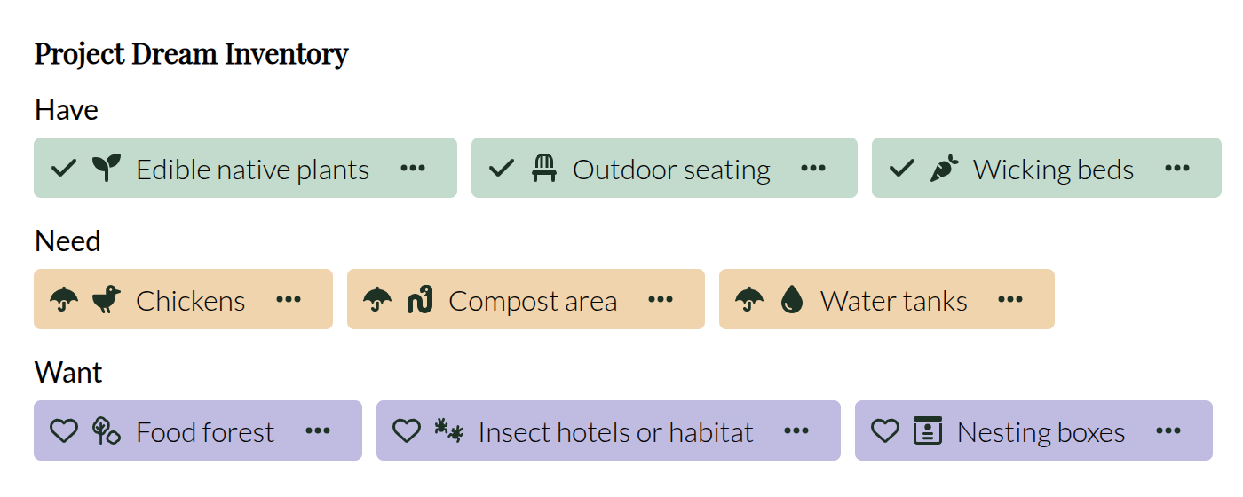
During initial site planning, project goals translate into concrete inventory items grouped under ‘Haves’, ‘Needs’, and ‘Wants’. Each inventory item links directly to a corresponding concept area type, establishing clear spatial boundaries on the canvas before fine details are added.
In the example below, you will notice that we placed existing assets where they are currently located or where we know they belong. For remaining unplaced or future inventory items, we used concept areas as floating placeholders so we can assign relationships between them in the next step to clarify their placement.
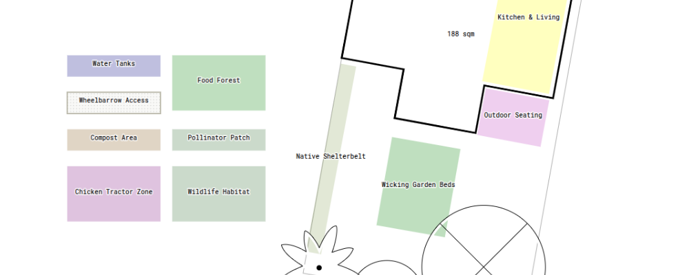
When deciding which tool to select, choose from predefined colour-coded types. The table below outlines common wishlist elements represented within each concept area. You can change the area type and corresponding colour anytime.
| Concept Area Type | Purpose | Common Elements |
|---|---|---|
| Water Related | Harvesting, storing, and filtering water | Rainwater harvesting tanks, contour swales, storage dams, greywater diversion systems, bio-filtration wetlands, overhead header tanks |
| Access | Movement, delivery, and equipment access | Vehicle driveways, wheelbarrow tracks, delivery turnaround bays, equipment corridors, pedestrian entry paths |
| Shelterbelt | Microclimate buffers and wind protection | Multi-layered windbreaks, privacy screening hedges, fire-retardant green belts, dust barriers, timber belts |
| Building | Dwellings and primary structures | Primary houses, garages, greenhouses, shade houses, workshops, covered verandas, storage sheds |
| Nature | Conservation and ecosystem restoration | Wildlife conservation corridors, pollinator gardens, frog ponds, insect hotels, native bush pockets, bird nesting groves |
| Utility | Material processing and tool storage | Compost bays, worm farms, tool sheds, propagation stations, biochar processing hubs, soil staging areas |
| Animal Related | Livestock housing, care, and foraging | Chicken coops, deep-litter runs, mobile forage pens, beehives, duck ponds, small livestock paddocks |
| Social | Living, gathering, and outdoor leisure | Outdoor seating areas, fire pits, dining decks, covered pergolas, outdoor kitchens, play lawns, garden retreats |
| Garden | Food, biomass, and plant production | Wicking beds, kitchen vegetable patches, multi-layered food forests, herb spirals, berry patches, syntropic agroforestry blocks |
Example of Progressively Mapping Concept Areas in Permiehub
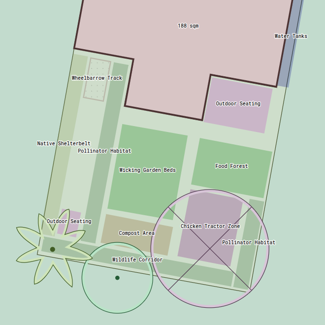
In our example site layout, we mapped core concept areas across our canvas:
We began by selecting the Garden tool from the Concept Design overlay to position wicking beds in Zone 1 near the kitchen door and a multi-layered food forest in Zone 2. We then selected the Utility tool to locate the compost area along main walkways where soil amendments are needed most.
Next, we selected the Water tool to position rainwater tanks adjacent to roof catchments, followed by using the Animal tool so the chicken coop borders both the compost area and the food forest.
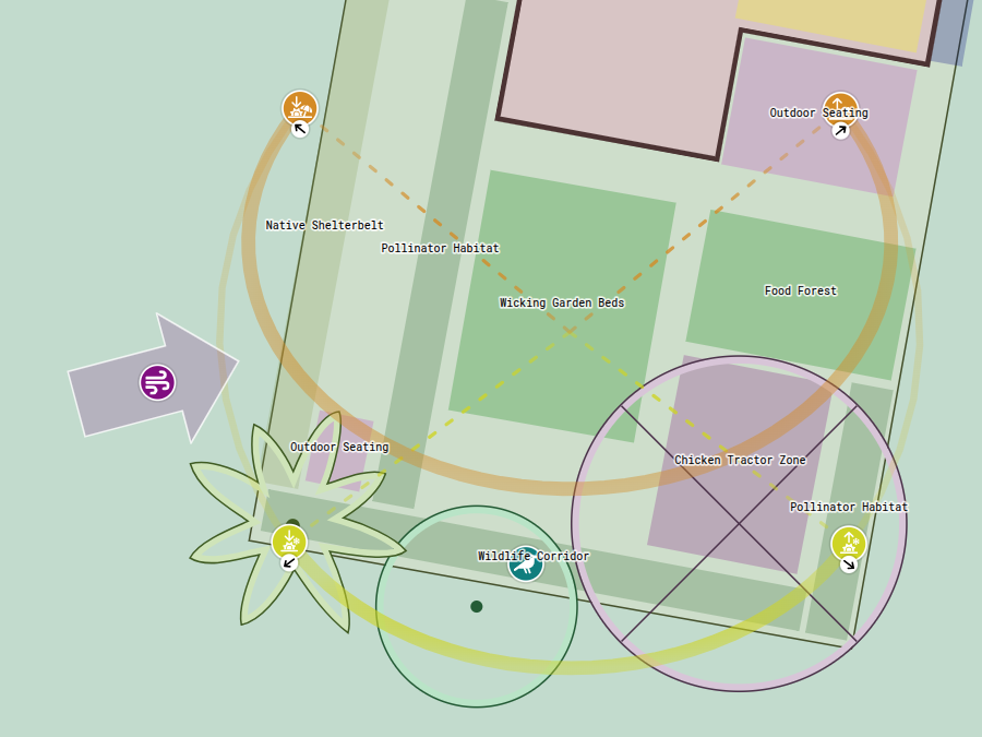
We then used the Social tool to set up an outdoor seating area with clear views across the site, framed the perimeter using the Shelterbelt tool for wind shelter, and mapped the Access tool to designate wider wheelbarrow tracks. Finally, we picked the Nature tool to reserve pollinator habitats before using the Building tool to position the primary residence.
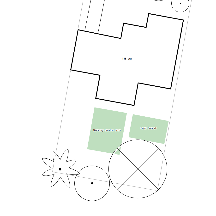
Drawing garden concept areas for wicking beds and food forest
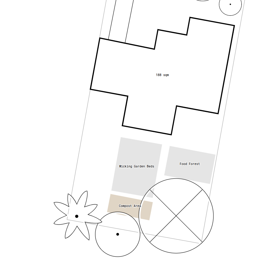
Placing utility concept area for compost bays or tumblers
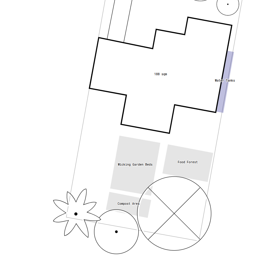
Positioning water related concept area for rainwater storage tanks
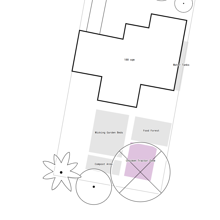
Locating animal related concept area for chicken run
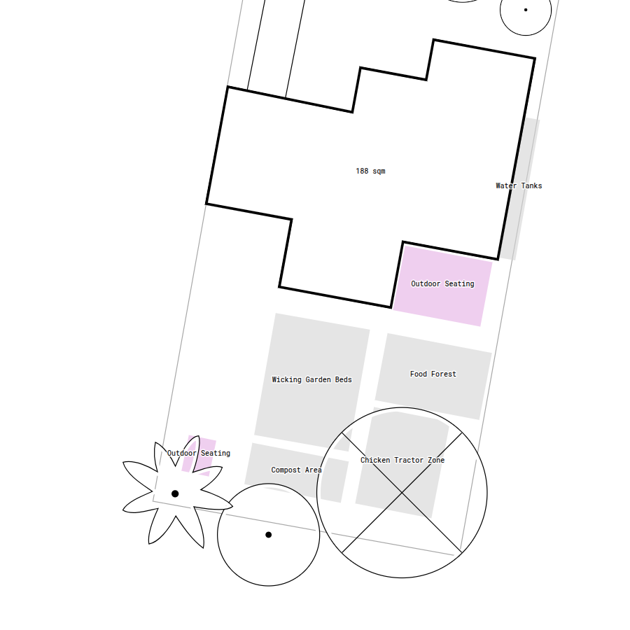
Adding social concept area for outdoor seating and gathering
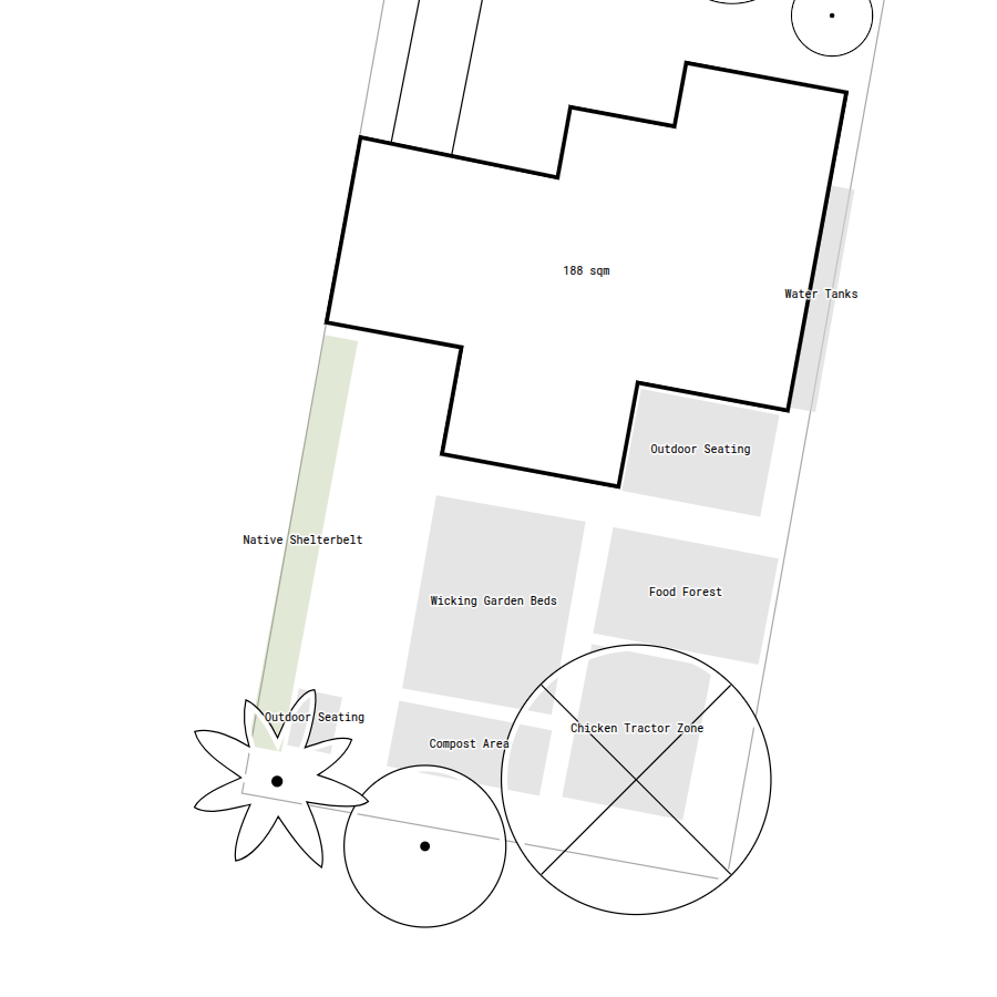
Outlining shelterbelt concept area for native windbreak planting
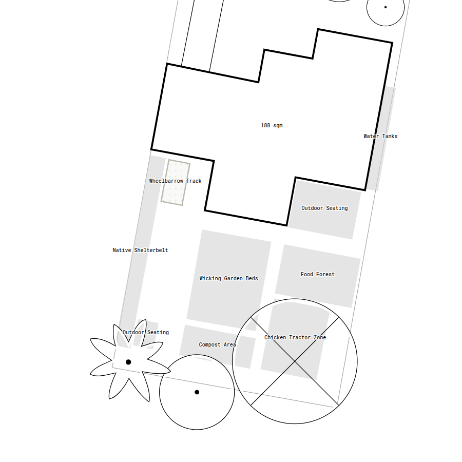
Mapping access concept area for wheelbarrow or larger equipment
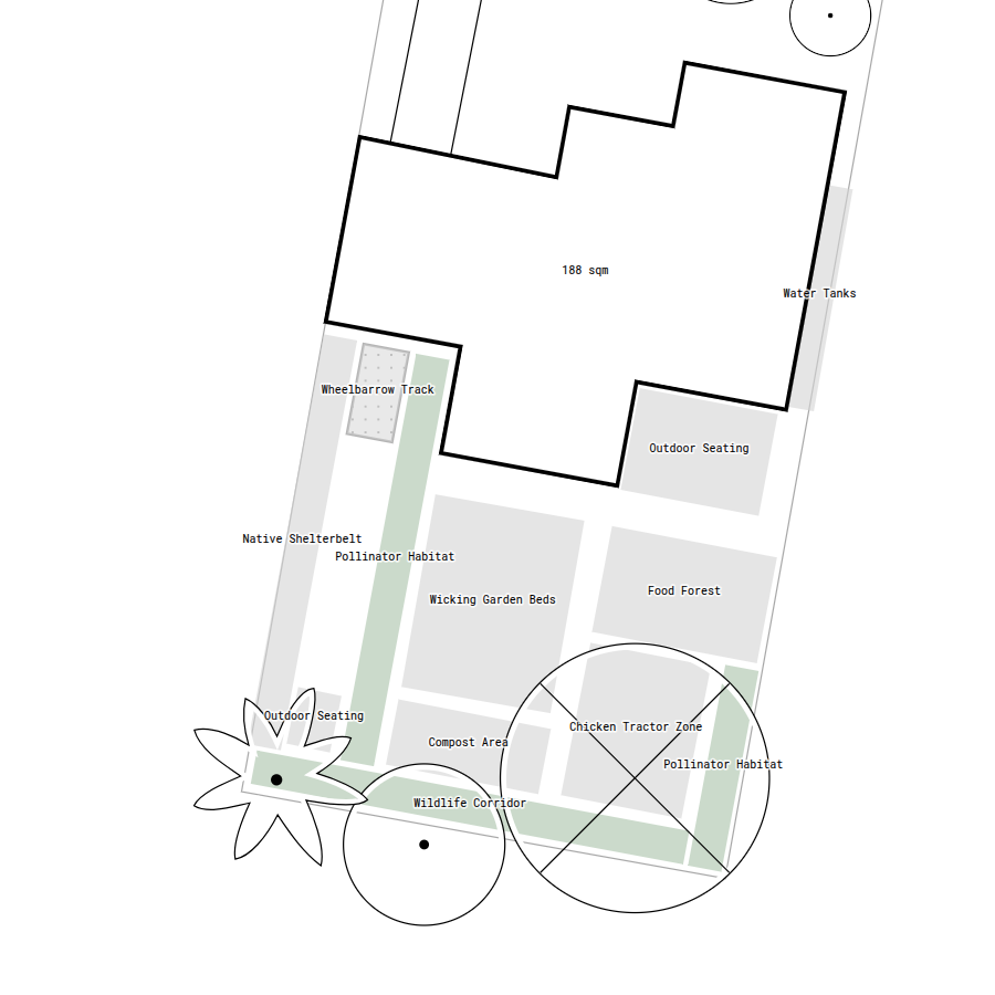
Designating nature concept area for pollinators and backyard wildlife
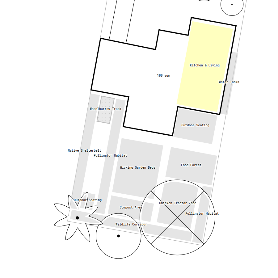
Placing building concept area for kitchen and living space
Step 2: Map Inputs, Outputs, and Resource Flows
Creating strong connections between site elements minimises maintenance and maximises yields across your site. Reviewing how nutrients and energy travel between features ensures that outputs from one area directly satisfy the inputs required by another.
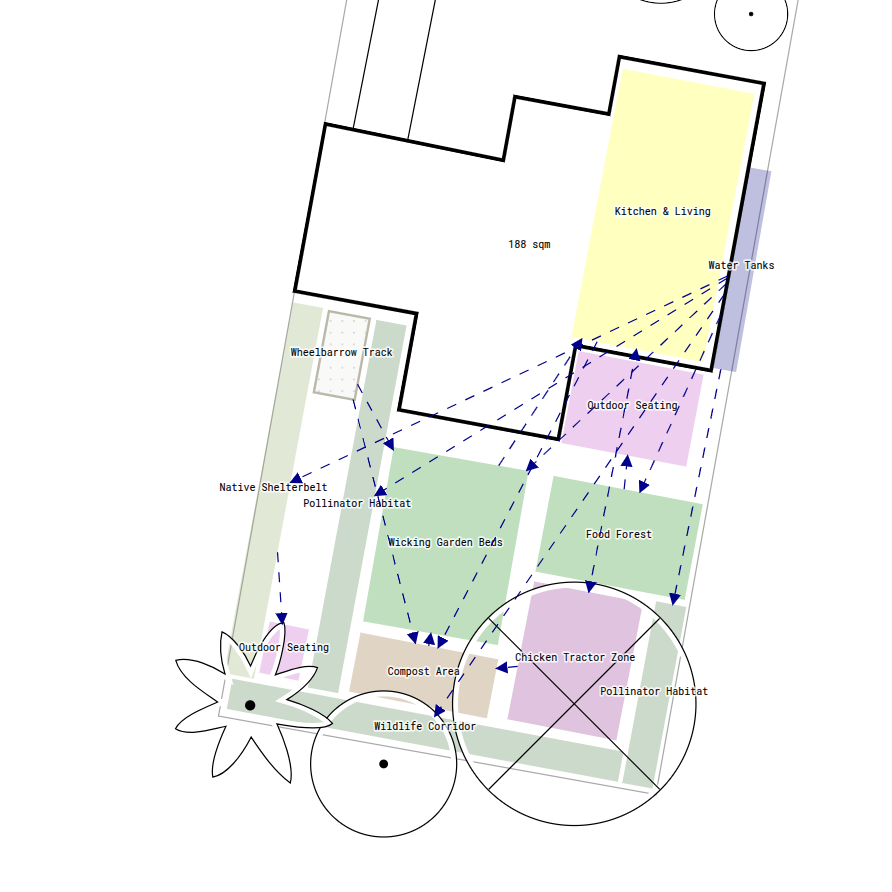
Using the wishlist established in your design vision, map functional relationships between existing site features and future elements. While fixed features stay in place, mapping resource inputs and outputs reveals the ideal relative location for floating placeholders or roughly placed concept areas, guiding you to fine-tune their final positions on your canvas. Connecting concept areas through functional relationships organises your space efficiently and saves valuable time on daily chores.
Example of Using Relationships to Position Concept Areas
In our example layout, we converted wishlist items into concept areas and kept several as floating shapes beside the site boundary where exact positions were uncertain. By drawing resource flow lines, such as connecting water tanks to garden beds or compost bays to chicken runs, the ideal relative locations became clear, allowing us to move every concept area onto the canvas map with confidence.
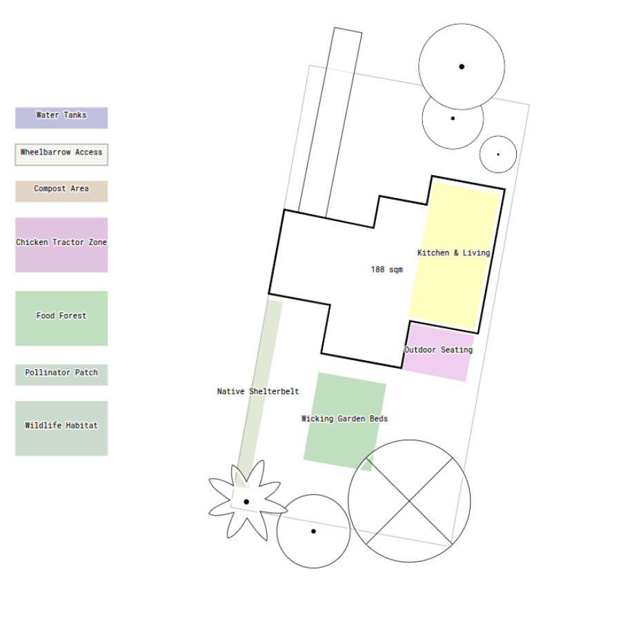
Wishlist inventory items converted into concept areas and labeled
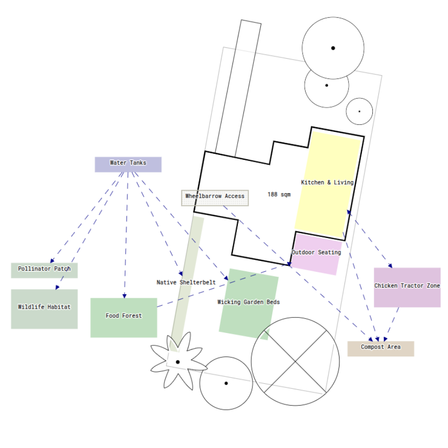
Functional relationship mapped between existing and planned areas
Areas placed to position with relationships, site, and access in mind
Example of Progressive Relationship Mapping in Permiehub
With our concept areas placed across the site, we mapped resource flows to test and confirm their positions. We began building closed resource loops by routing daily kitchen scraps straight to the chicken run, with manure and soiled bedding moving directly into the adjacent compost bays. Next, rich finished compost from the utility zone feeds nutrient-hungry crops in the wicking beds and top-dresses the food forest. Fresh produce and blooms provide visual beauty to the outdoor seating area during social gatherings. Mapping these resource flows confirmed that our overall layout minimises daily foot traffic while gravity-feeding rainwater to all production zones.
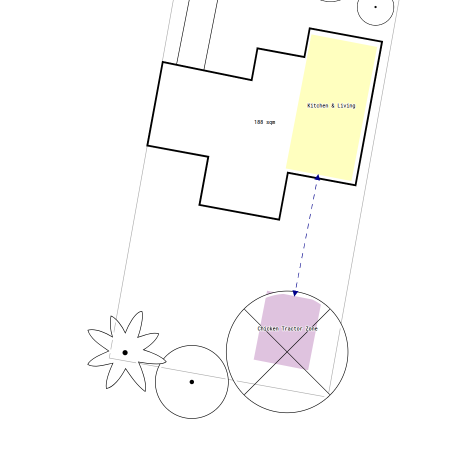
Resource flow connections linking kitchen and chicken run
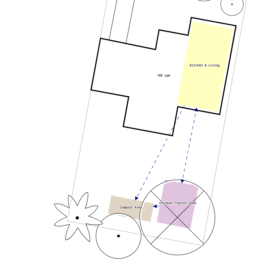
Nutrient transfer lines from kitchen and chicken run into compost bays
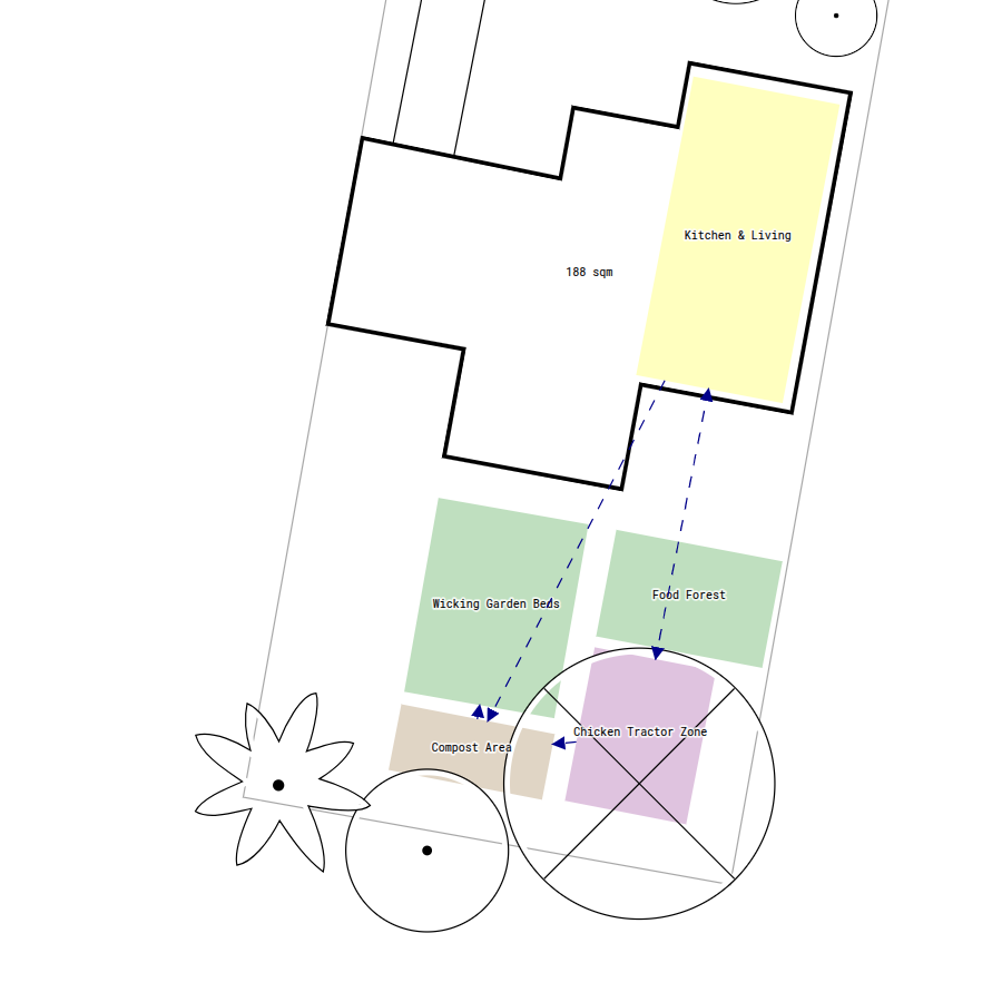
Fertiliser distribution from compost to garden beds and food forest
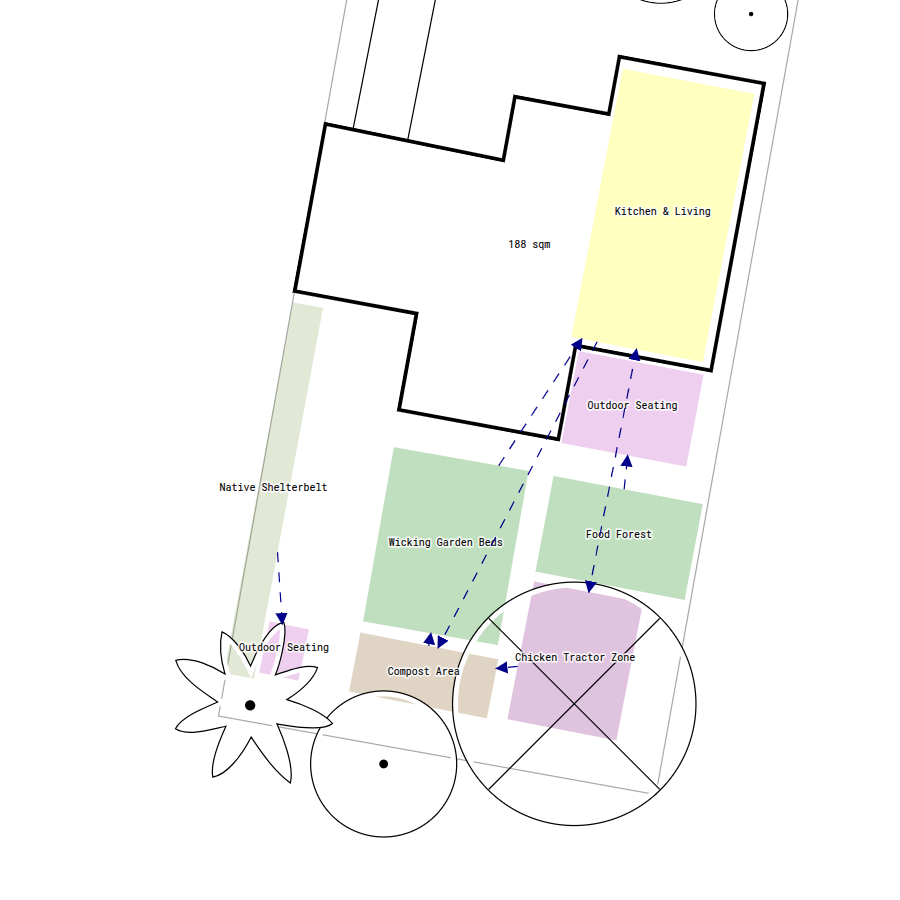
Harvest and beauty provided by green spaces to social seating area
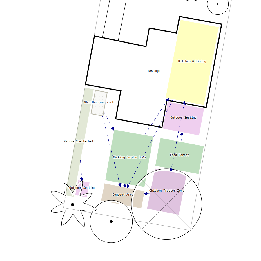
Bulk material entry routes to the garden or compost area
Irrigation provided from water tanks to green spaces
Step 3: Connect Communication Pathways
Organising your pathways into functional circuits saves time and effort on daily tasks. Using the Communication Pathway Tool, you can route distinct paths to accommodate different levels of traffic, equipment sizes, and activity types across your landscape.
Types of communication pathways you might want to mark out on your site include:
- Daily harvest pathways connecting primary house entrances directly to wicking beds, kitchen gardens, and herb spirals for rapid daily produce picking.
- Composting pathways linking kitchen doors to compost bays, worm farms, and chicken runs to simplify waste recycling.
- Material access pathways providing wide, clear routes for wheelbarrows and equipment between driveway delivery points, storage sheds, and garden beds.
- Animal management pathways connecting coops, forage runs, and water points to streamline routine feeding and daily care.
- Leisure loops weaving through social gathering spaces, native shelterbelts, and food forests for relaxing garden strolls.
Example of Mapping Communication Pathways in Permiehub
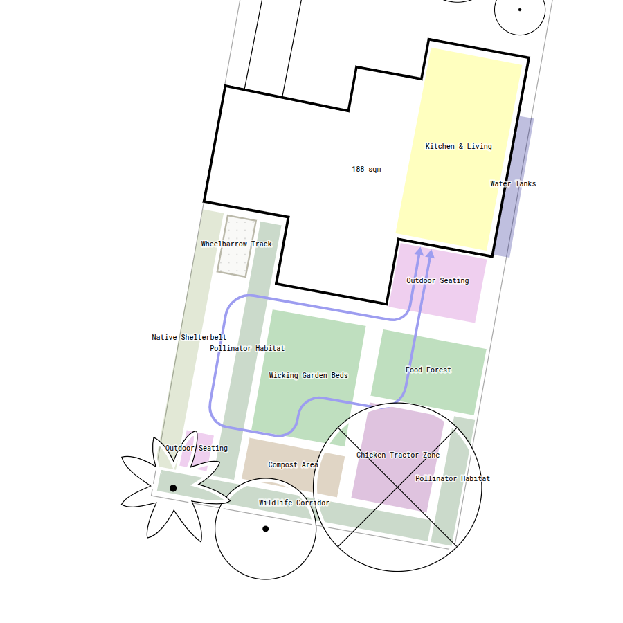
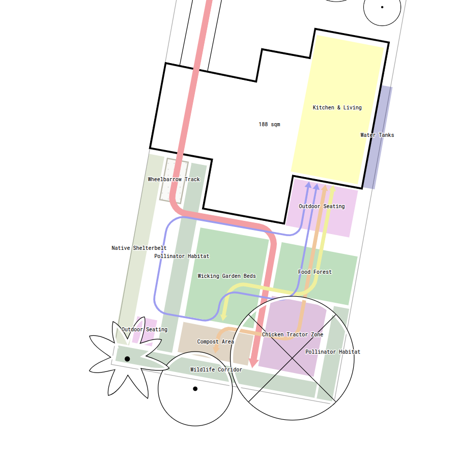
In our example layout, we used the Communication Pathway Tool to map distinct pathways and streamline daily tasks across the site. We used both line colour and thickness to convey the frequency and clearance of the path. Arrows at one or both ends help visualise the movement.
Incoming material deliveries, shown in red, move from the front of the house through the garage into the backyard via wheelbarrow access to bring in extra mulch, compost, soil, or new plants when establishing gardens, as we grow plenty of biomass on site and use chickens to generate fertiliser.
The harvesting communication pathway, marked in yellow, connects the kitchen directly to the wicking beds and food forest for daily produce picking. We made the line narrower to indicate a route taken on foot without a wheelbarrow.
The composting communication pathway, shown in orange, links the kitchen to the compost bays and chicken run for organic waste management. We used a shade closer to red to mark a route with larger materials moving through.
Finally, the leisure loop, shown in blue, weaves through social areas, the food forest, around the chicken run, and past garden beds for relaxing garden walks. The leisure pathway line is the thinnest as the others will be used more frequently.
Leisure pathway creating a relaxing walking circuit through the site
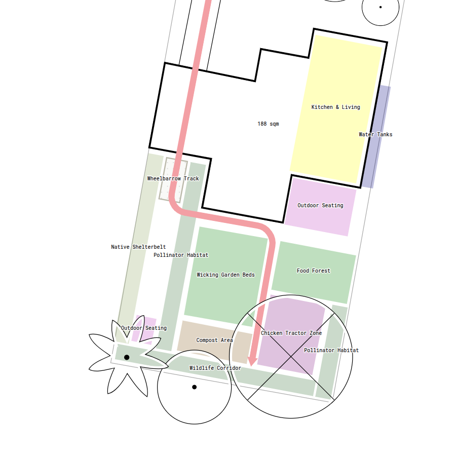
Material access pathway mapped for wheelbarrow route
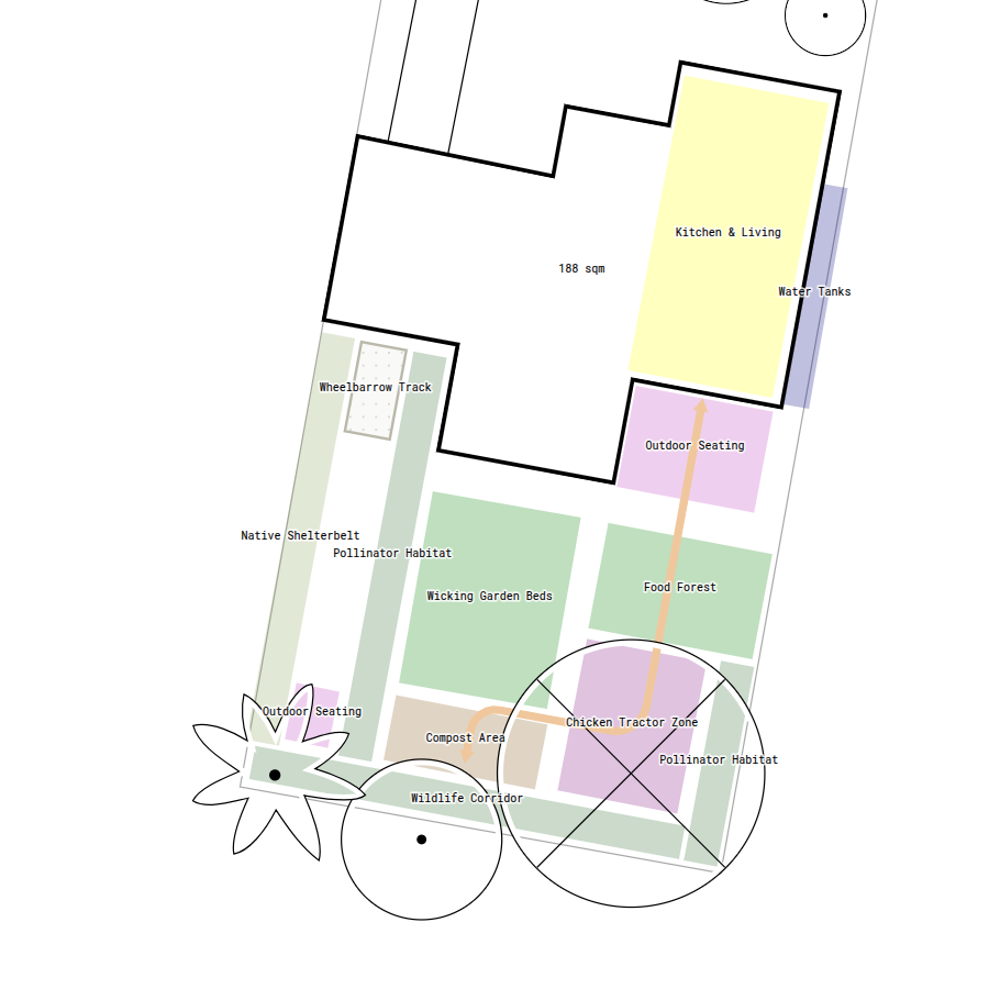
Nutrient cycling route between kitchen, compost, and chicken run
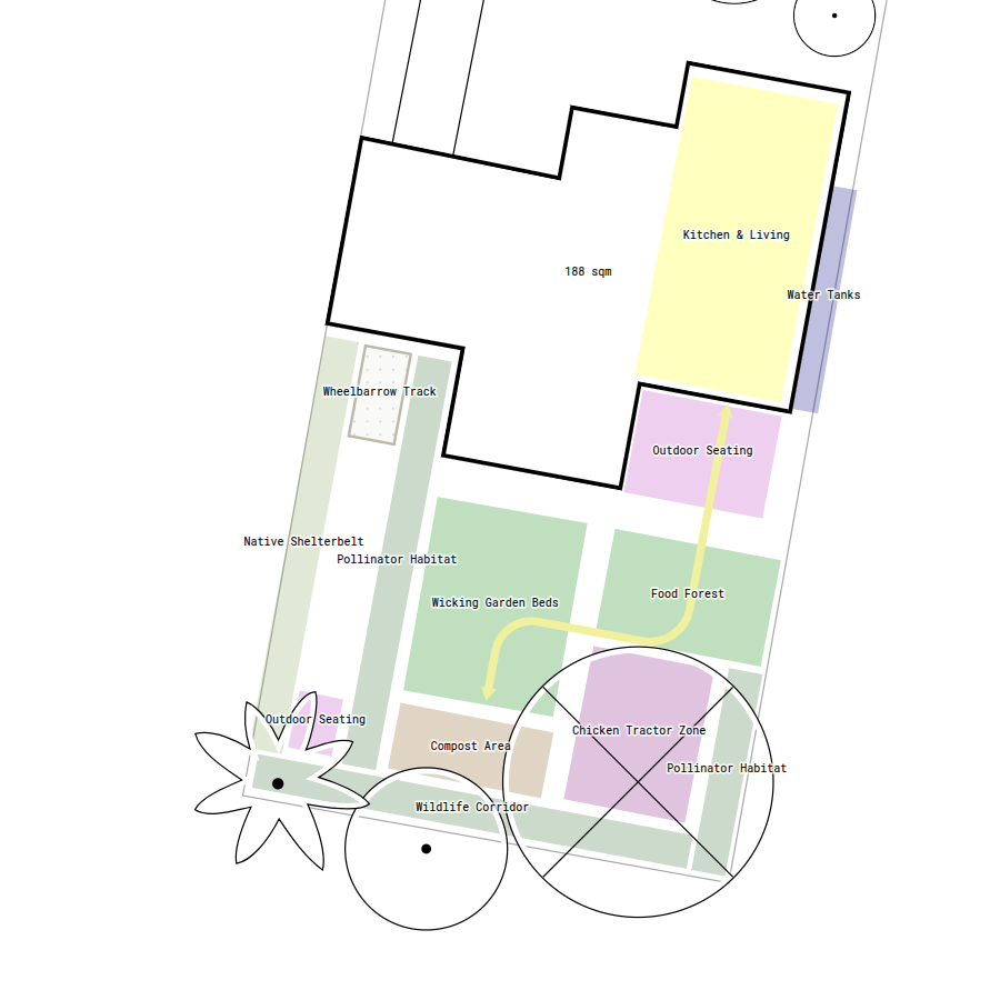
Daily harvest pathway connecting kitchen to productive beds
Complete network of communication pathways
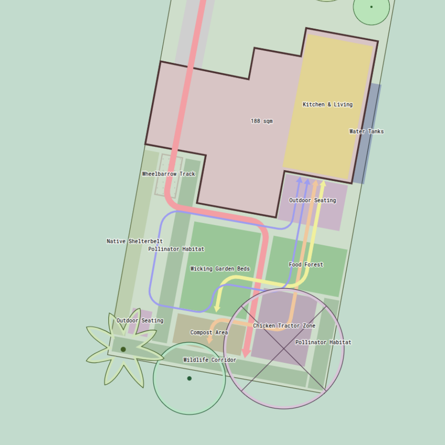
Colour-coded communication network on top of base map
Next Steps: Add Details to Concept Layouts
With your vision items mapped into concept areas, resource flows linked, and communication pathways drawn, you are ready to assemble your complete site plan. Now you can place details in each area and tackle your project step by step. Explore detailing design topics in the Permiehub Help Centre.