How We: Map Land
An accurate map provides multiple benefits, as it acts as a foundation for design and helps place elements that support the land, its inhabitants, and its visitors. However, the process of mapping land to create a base map might feel like a daunting task. Fortunately, we can use a variety of techniques and tools to describe the physical features of a site.
Estimated reading time: 14 minutes
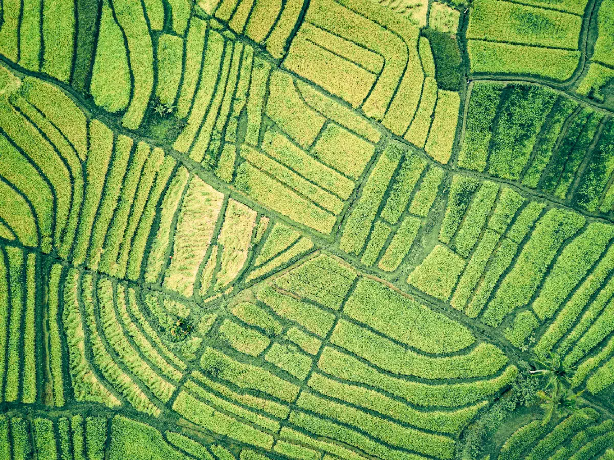
Above: Aerial imagery reveals how terraced fields follow natural contour lines. Mapping these features helps us create level planes on sloped ground to manage water, prevent erosion, and retain nutrients.
When mapping, we start a cycle by reading the land or looking at a map, identifying known points first. Those then inform us of the positions of points with unknown locations. Drafting their relative positions completes our map.
1. Finding Points of Reference
Creating a map representation of a block of land might begin by identifying known points that already exist on it. We can use an absolute point in space via GPS with latitude and longitude coordinates, or use relative points of reference that are visible to the eye. Common reference points for drawing the land’s base map include:
- Boundaries of a suburban block or existing fence lines.
- Buildings and their specific dimensions.
- Distinct paddock trees on rural blocks.
- Dams or rivers.
- Tops of hills or bases of gullies.
Learn how to automatically add aerial imagery, property boundaries, contours, and other features to a base map.
2. Mapping Terrain
When mapping terrain, we account for slope. Determining slope by eye can be deceiving. We walk the land to feel the slope in our feet, but for accurate measurements of the steepness of the slope and to identify contour lines, we need more tools.
A contour line, sometimes shortened to contour, represents the intersection of the land with a virtual plane at a specific height above sea level. Finding points at identical elevation that form contour lines is vital for designing swales built along them to slow down water and allow it to infiltrate the soil. They improve the land’s water-holding capacity, supporting plants during droughts and preventing nutrient run-off during floods. Interestingly, and perhaps not surprisingly, people sometimes use the word contour as a synonym for a swale built on a contour line.
Finding Contour Lines
When creating a water-holding swale, ensuring points on the contour are level with each other is often more important than knowing the exact elevation above sea level.
Walking Contour Lines Using A-Frame Tool
An A-frame tool is a practical choice for this task. We constructed a portable version from three straight, lightweight pieces of timber, three wing nuts with bolts, and a piece of string with a heavy nut threaded at the end. Two pieces of wood create the legs of the A-frame, while the third acts as a cross-beam. We ensured we attached the cross-beam at the same height on each leg. Because the two legs are symmetric, the weighted string sits in the centre of the shape when they stand on even ground.
How do we use an A-frame? We start at an identified reference point or a location where we wish to create a levelled line. We place one leg directly at the point and rotate the second leg around it until the string stops at the centre of the frame. Where the second leg falls becomes our next point. We then rotate the first leg around this position to find the third point, repeating the process until we reach the end of our design.
Waiting for the string to settle took a long while, so we think next time, attaching a spirit level to the centre beam might shorten the process.
Finding Contour Lines Using Water Tube Tool
The water tube levelling tool relies on water to self-level in a clear tube attached to a piece of timber or a picket on each end. To prepare for measuring, we fill the tube with water and ensure the timber pieces have identical height markings starting from their bottom edges.
Similar to the A-frame tool, we start at an identified reference point or a location where we wish to begin tracking a particular contour line. Even if we do not know the exact elevation, this point might be the start of our swale, for example.
As the water surface in the tube will always indicate the same level, we compare the distance from the ground on each end. We find the next contour point by moving the second timber piece until the water reaches the same distance from the ground as it does on the first piece. When measuring, we make sure both timber pieces are pointing straight down with the help of spirit levels. To prevent compounding errors when moving the tube to the next point, we keep one end of the tool in position for as long as the length of the tube allows.
In comparison with the A-frame tool, the water tube tool allows us to measure longer distances. We benefit from the water’s ability to inform us of differences in height even when we are not measuring contour lines, but instead determining the slope between them or indeed any two points.
Locating Contour Lines Using Automatic Digital Laser Level
A digital alternative is using a laser level set to the specific height we wish to detect. We rely on a vertical target staff equipped with a receiver, which must be held perfectly vertical. We move across the land with the target receiver while the laser level provides an indication with beeps, and the frequency increases as we get closer to the target height.

Finding Contour Lines Using Water Tube Tool
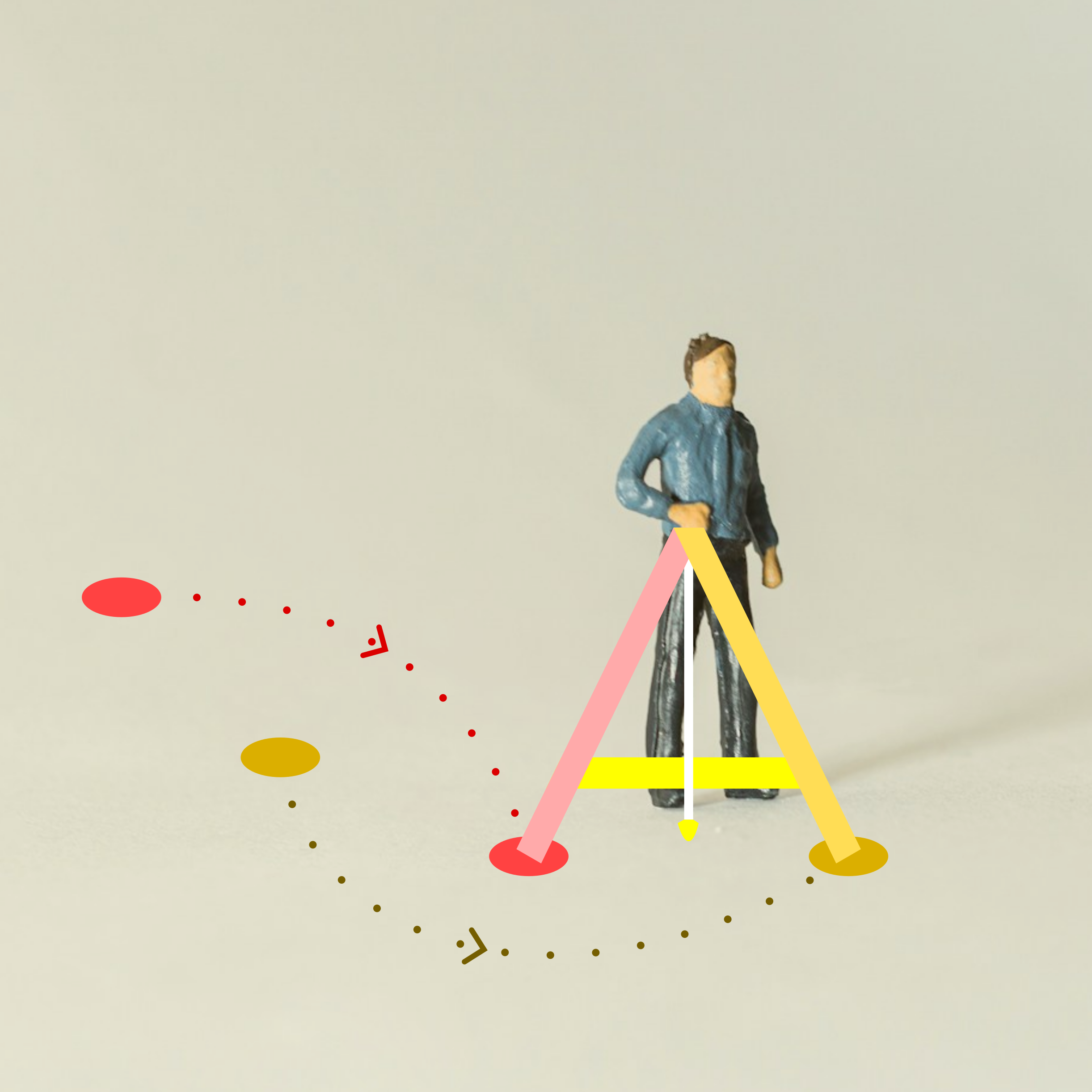
Walking Contour Lines Using A-Frame Tool
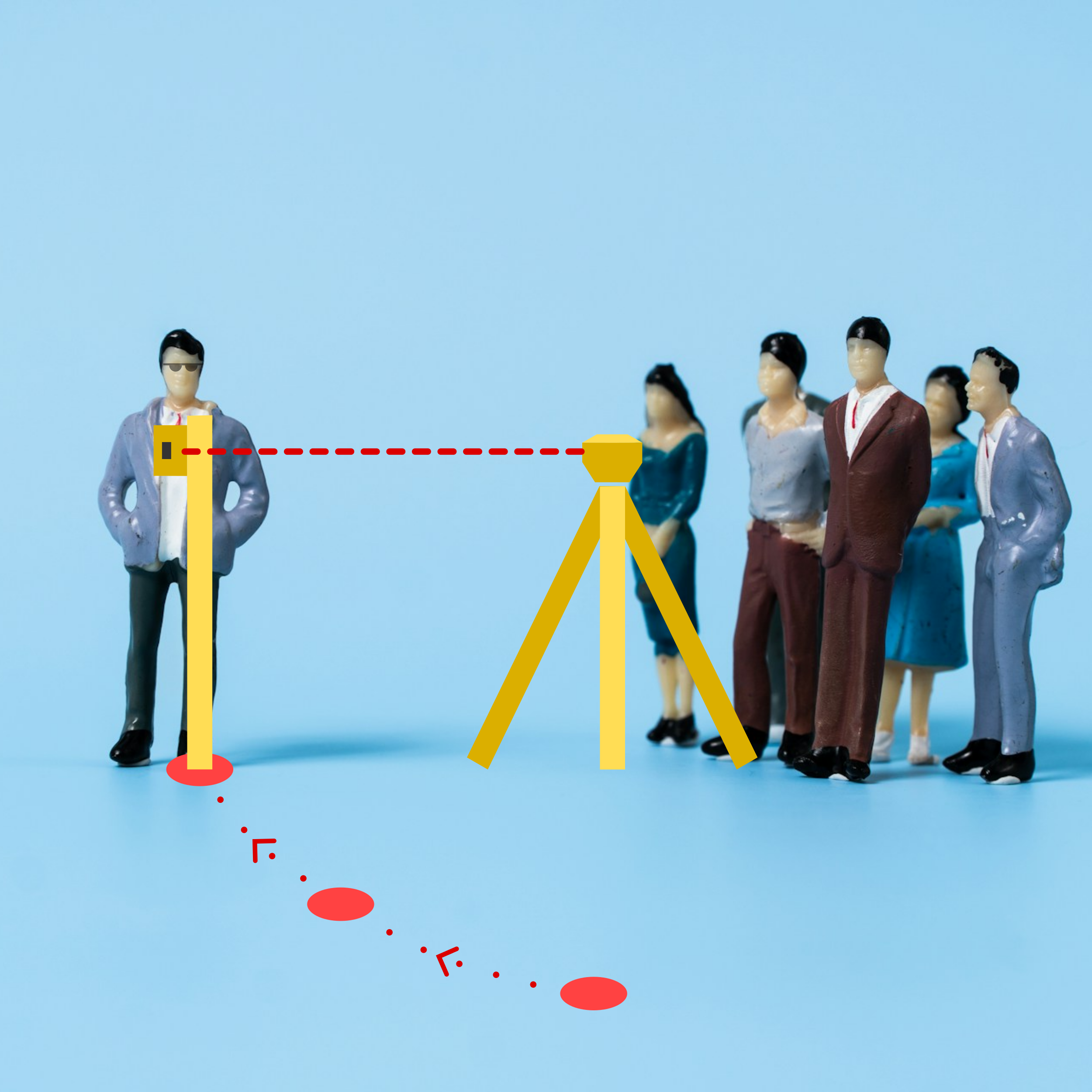
Locating Contour Lines Using Automatic Digital Laser Level
Interpreting Contour Lines
Before we get into tracing contour lines back to the map, we might want to understand what they represent. The trio of images below shows some common features of the landscape as characterised by contour lines.
Hilltops
A contour line forming a closed loop that contains no other loops and has a higher elevation than the lines around it represents the top of a hill.
River Streams Through Valleys and Gullies
Rivers originating at mountaintops will likely be found in gullies and valleys, as they have eroded the soil along their path. These are identified by contour lines with decreasing elevation that curve into the hillside, often forming a V or U shape pointing uphill.
Ridges Sloping off Hilltops
The land feature typically found alongside a gully is a ridge, with contours describing the descent away from the hilltop. In this case, the curves in the lines point downhill rather than toward higher ground.
Hilltop
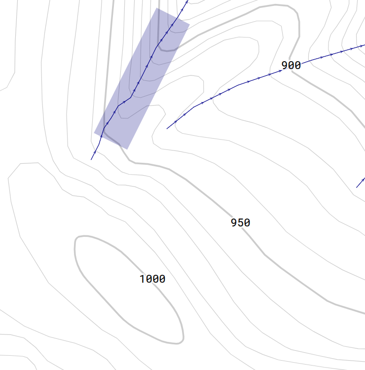
Stream Through Valley
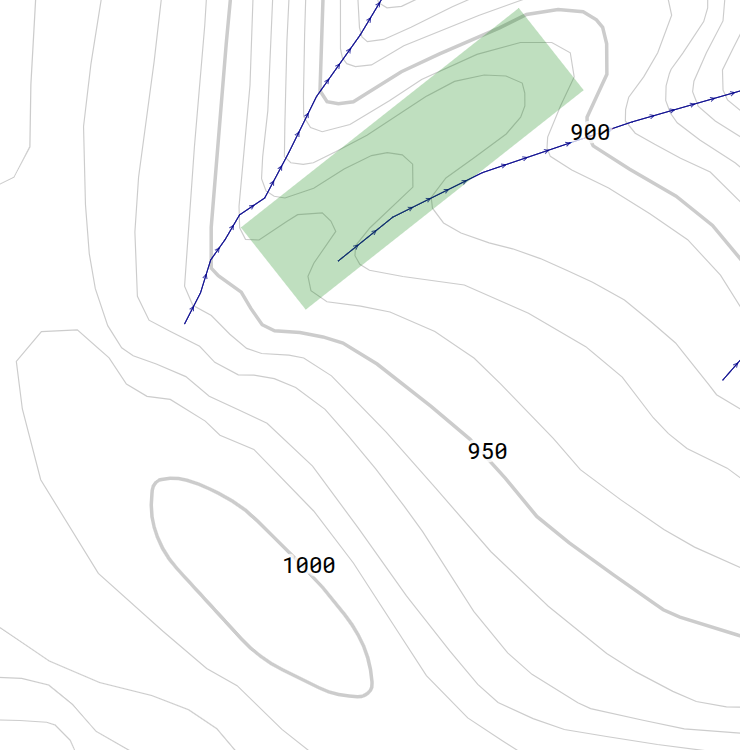
Ridge Sloping off Hilltop
Determining Slope Between Contour Lines
The ratio of the difference in elevation between two contour lines to their horizontal distance provides the grade of the slope. To measure the difference in elevation in the field, we can use some of the techniques applied for finding contour lines or determining horizontal distances.
Finding Height Differences Using Water Tube Tool
Similar to finding two points with the same elevation using a tube filled with water, we can use the tool to determine the height difference between two locations. Both timber supports at the ends of the tube are the same height and marked identically. We can see how the water level matches when we place them next to each other on level ground, which confirms our starting point.
When the timber supports or staffs stand next to each other on level ground, we can either measure the distance from the bottom of the staff to the initial water level or make a mark. If we plan to use the tube tool for more than a few measurements, we can also take the time to mark out heights on the staff itself and take a reading.
When measuring the difference in elevation between two points, we place one support at a different height than the first. We shake out any bubbles in the tube that might distort the readings. Because the water in the tube self-levels, it reaches a higher point on the support at the lower elevation and a lower point on the higher end. We can find the exact change in elevation by calculating the difference between these two final readings.
Additionally, because the water level at each end moves in opposite vertical directions by an equal length, we can add these distances together. Alternatively, we can simply measure the distance from our initial mark to the new water level on one support only and double it.
Example of Using the Water Tube Tool to Measure Elevation Difference
In this example, we want to measure the height between a raised garden bed edge and the ground. We fill the tube and the measurement reads 4 feet while the staffs stand next to each other. This means there is a total of 8 feet of water in height measured on the timber supports. We then place one staff on top of a 2-foot tall garden bed edge.
Because the water must self-level, the staff on the lower level now has to match the height of that 2-foot garden bed. Out of the total 8 feet of water we measured initially, the remaining 6 feet of water will distribute evenly at each end of the tube. Therefore, the staff elevated by 2 feet now reads 3 feet of water, and the bottom support measures 5 feet to the water level.
Both ends of the tube changed by 1 foot, which corresponds with the total change in elevation of 2 feet between the two staffs. We can confirm this by calculating the difference between the two new readings, where 5 minus 3 results in 2 feet. While we can simply measure the height of the garden bed in this instance, this method becomes far more valuable when trying to see the difference in elevation across a whole garden area.
The trio of images below shows how the water level stays the same at an identical elevation, but changes symmetrically when moving between different contour lines. The person at the bottom of the third image holds a timber support where the water has increased by one unit on the measuring staff, while the water level for the person at the top has dropped by one unit. We can deduce the height difference between these two points is two units of measurement.

Water Level Matching at Identical Elevation

Water Levelling Along Contour Line Elevation
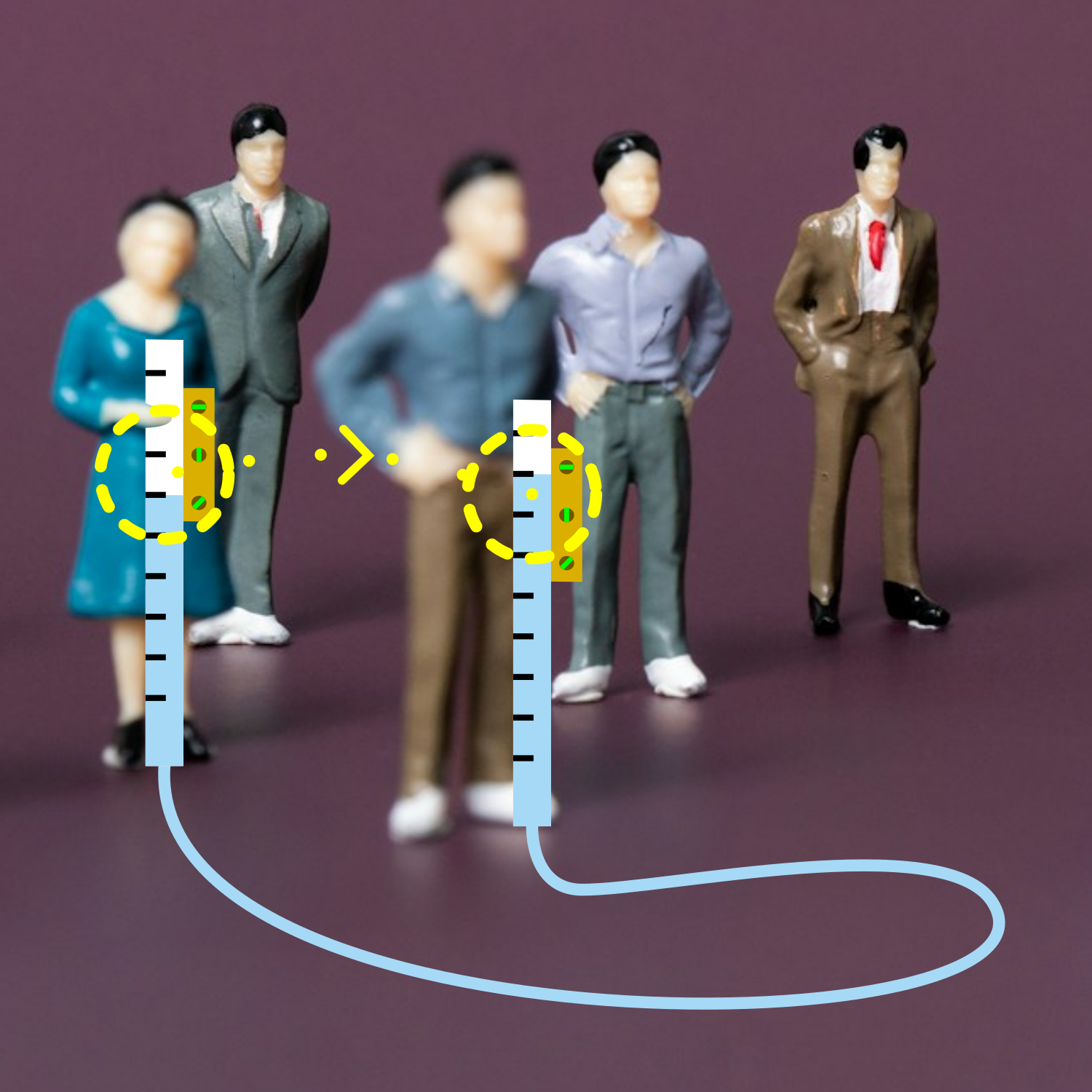
Measuring Elevation Difference Between Contour Lines
Measuring Height Differences Using Non-Stretch String with Line Level
To determine the slope between two stakes with a clear direct connection between them, we can use a non-stretch bricklayer’s string and check that it is level with a line level. We tie the string to one stake and then loosely to the other. Using the line level, we adjust the loose end to ensure the two ends are level. We can then mark the two spots at each end of the string onto the stakes. At the stake at a higher elevation, the mark will be closer to the ground than at the stake at a lower elevation.
We measure the difference by measuring the distance from the ground to the mark on each stake. The difference between these two height readings corresponds with the difference in elevation. If the values match, it means we found two points on the same contour line and there is no height difference between them.
Because the string is already level, once we know its length and have measured the elevation difference, we determine the ratio of the two to calculate the slope.
Determining Slope Using Laser Measure with Inclinometer
We can take advantage of technology with a simple handheld laser measure if it is equipped with tilt detection. We find two stakes and place them straight with the help of a spirit level. We then mark the same distance from the ground on each stake.
We position the laser measure on the first mark as accurately as possible. By pointing from the first mark to the second, the beam will essentially copy the angle of the ground. Thanks to the inclinometer of the laser measure, the device will show the angle of the slope between the two marks.

Finding Height Differences Using Water Tube Tool
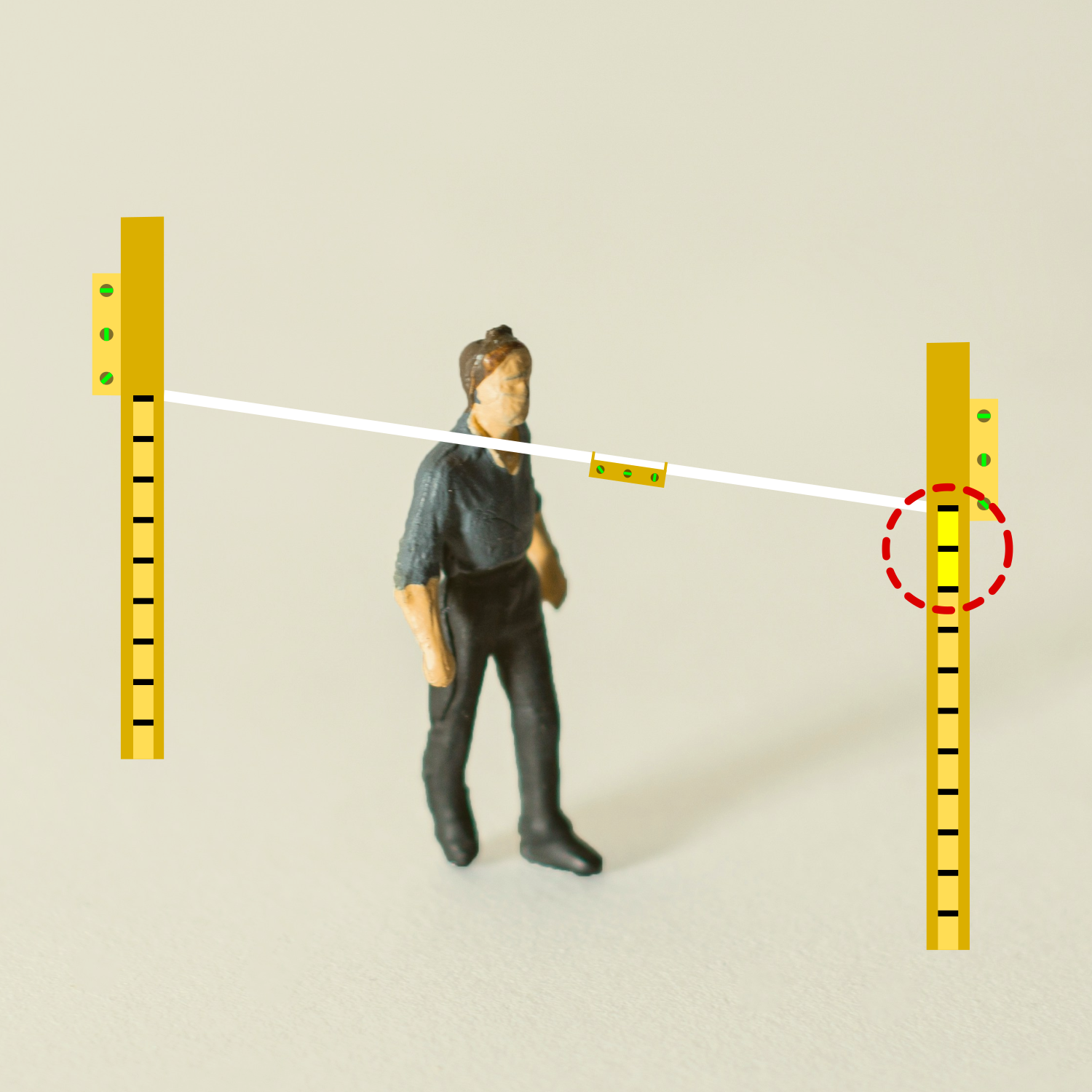
Measuring Height Differences Using Non-Stretch String with Line Level

Determining Slope Using Laser Measure with Inclinometer
Interpreting Slope from Contour Lines
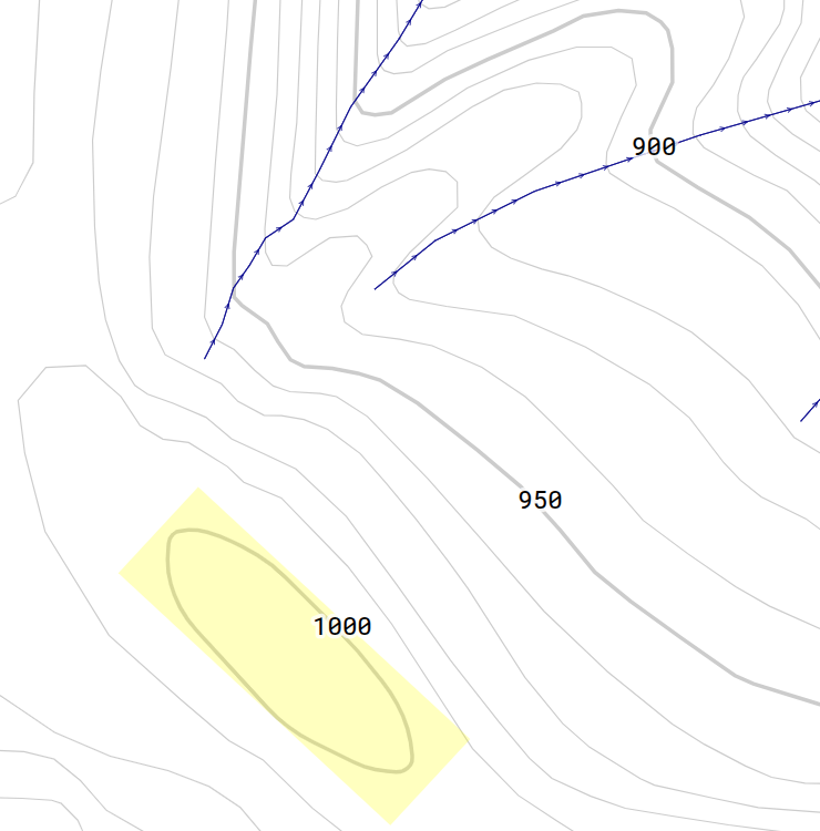
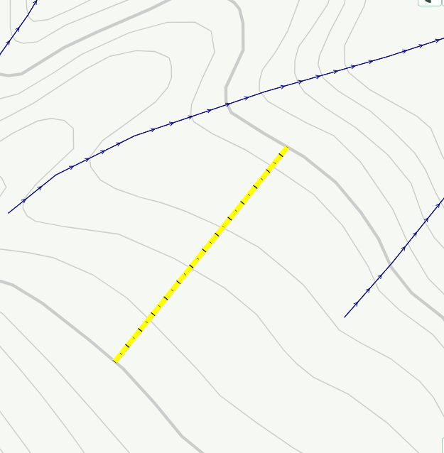
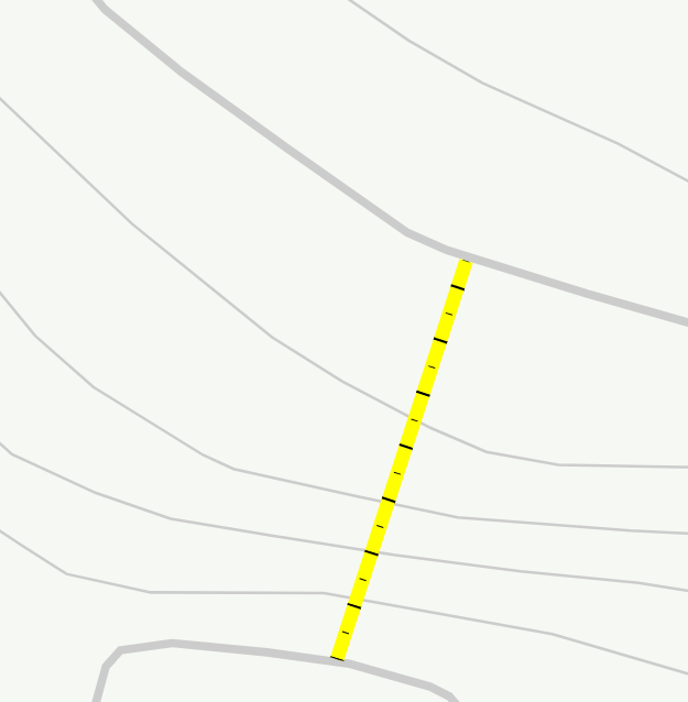
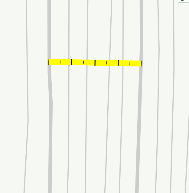
Below are examples of contour lines with major ones marked by a thicker line. The elevation difference between them is 50 metres. The yellow measuring tape shows the horizontal distance between these major lines. We can identify an abrupt, sharp slope where contours are close together and a slow, gentle slope where they are far apart.
Learn how to adjust contour lines imported via the Base Map Wizard and how to draw new ones.
3. Anchoring Features to Reference Points
Once we establish and mark the points for our map on the ground, we measure in relation to them. The process of determining the position of these points requires nearby reference points. Utilising the following tools and techniques allows us to map existing features accurately.
Tools for Transferring Field to Map
Measuring on sloped terrain can deceive, as the incline might skew the distance between two points. When we create a map, we must measure the distance on a level plane. Measuring in this way ensures the result is a projection straight down to the ground, parallel to the horizontal plane.
Measuring Level Distances Using Laser Measure with Inclinometer
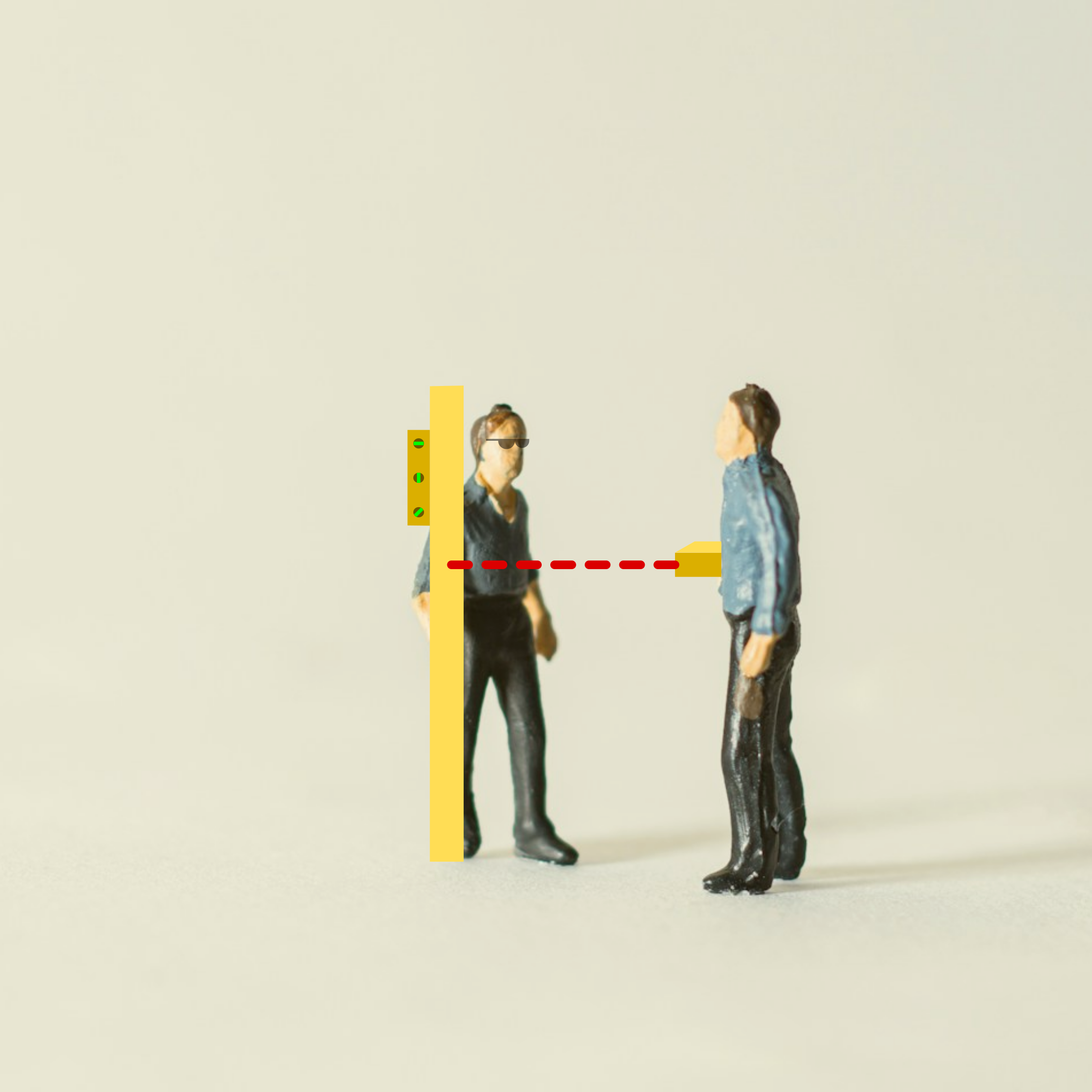
A handheld laser measure equipped with a tilt sensor offers an efficient way to measure distance while accounting for a slope. The device automatically calculates the horizontal distance between two points, requiring no additional effort from us.
Finding Distances Using Reel Tape or Non-Stretch String with Line Level
If a laser measure with slope compensation is unavailable to us, we can use a reel tape measure with a string level attached or a spirit level gently held parallel to it. By also making sure the two points of measurement are projected directly to the ground, we can be reasonably sure the line remains level between two points. If a tape is too short, we can substitute it for a non-stretch bricklayer’s string and measure its length between the two points afterwards.
Mapping Ground Markings with Drone Orthophoto
In addition to measuring distances to points with tools previously mentioned, a more tech-heavy option involves using a drone. We place stakes with painted tops in the ground where we need to mark a position, such as after we mark swales using an A-frame. Stakes are kept short, or we use a spirit level to prevent distortion in the vertical dimension. Another option involves attaching reusable markers or objects of high visibility to the ground.
After taking a sequence of photos with a drone, we stitch them together into an orthophoto. The result is an image perfectly perpendicular to the ground. Some processed drone footage might inherently carry information about the orientation and scale of the data, so we only need to align it to existing reference points on our map. If no such data are available in the image, we scale the image by the known dimensions of existing features, such as buildings or boundary lines.
Finally, we mark the position of the stakes on the image by tracing what we see. Previous processing of the drone photo into an orthophoto, combined with checking the scale, allows us to rely on the dimensions being reasonably accurate for building our garden projects.

Finding Distances Using Reel Tape or Non-Stretch String with Line Level
Measuring Level Distances Using Laser Measure with Inclinometer

Mapping Ground Markings with Drone Orthophoto
Follow this step-by-step process to plan drone flights, capture imagery, and process it into an orthophoto for seamless integration into Permiehub for project referencing and design.
Techniques of Transferring Field to Map
With the right tools, we can determine the position of points by relating them to known locations using the following techniques while working on the horizontal plane where all distances are level.
Triangulating Locations Using Distances to Known Points
We can confirm locations by taking measurements, ideally from two or more distinct points, using the level distance to each. By plotting the distance as a circle from each of these two points, we find the location at their intersection.
Plotting Positions Using Direction to Known Points
When the direct measurement is obstructed or the point is too far away, we can use a compass to record the direction of lines between two points. Drawing lines with the same angle reveals the location of our object.
Finding Perpendicular Distance to Fence Lines and Structures
When placing a feature near a known line, such as a fence or a wall, we measure the distance perpendicular to it. Measuring from the point of interest toward the line reveals the shortest distance. Using a ninety degree angle allows us to find the position of the object in relation to the line, though we often need a second reference point or line for full accuracy in two directions.
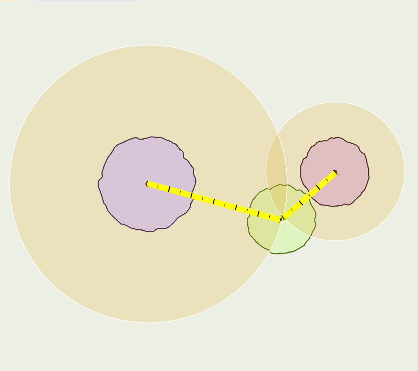
Triangulating Locations Using Distances to Known Points
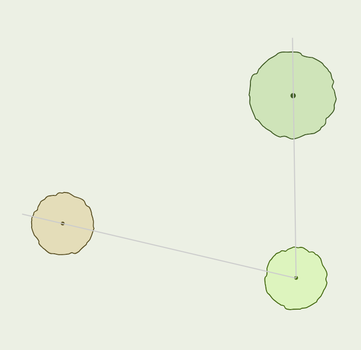
Plotting Positions Using Direction to Known Points
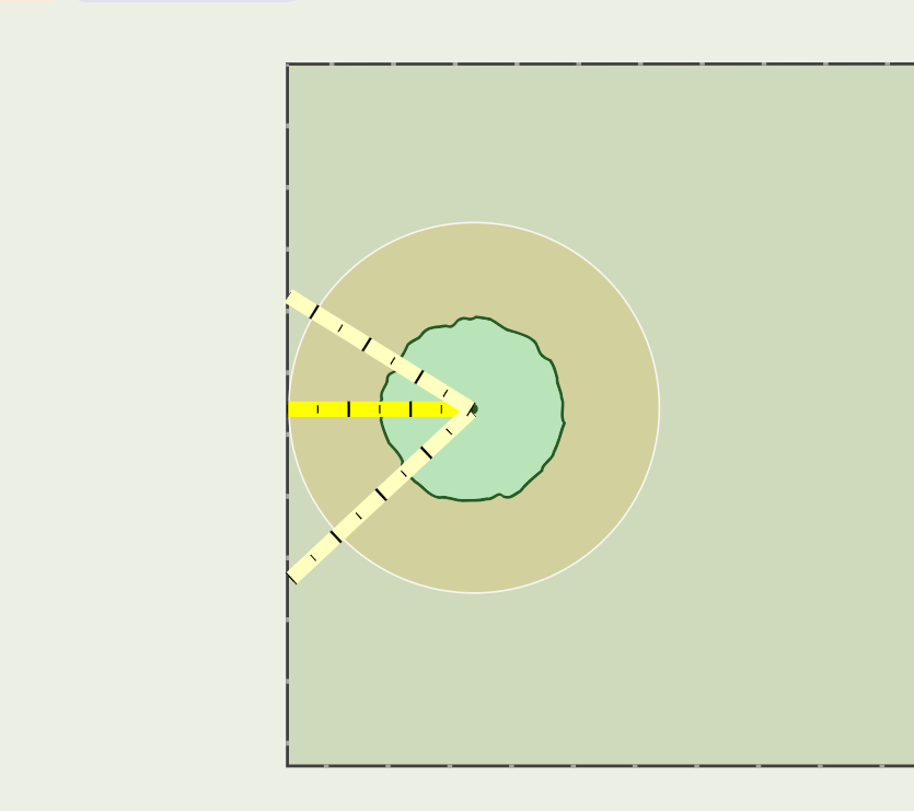
Finding Perpendicular Distance to Fence Lines and Structures
Learn how to upload and scale reference images, such as satellite imagery or a drone orthophoto, and discover how to scale them easily using only one dimension.
Thank You for Reading
We hope you will find this guide useful! Got feedback? Let us know at [email protected].